Construct and analyse truth tables (Exclude K-Map)
A truth table shows every possible input combination and the corresponding output. Uses: describe behavior of a logic gate analyse a logic circuit compare…
2 min read409 words
A truth table shows every possible input combination and the corresponding output.
Uses:
describe behavior of a logic gate
analyse a logic circuit
compare logical expressions
verify whether two circuits are equivalent
For n inputs → 2^n rows.
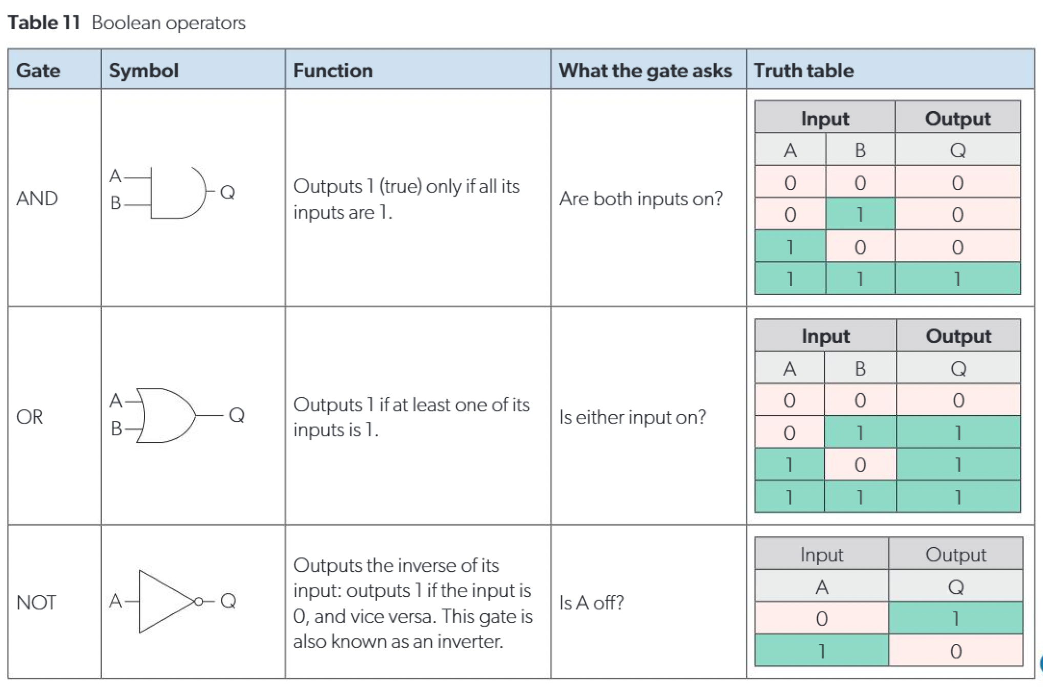
Standard truth tables
NOT gate
A
NOT A
0
1
1
0
AND gate
A
B
A AND B
0
0
0
0
1
0
1
0
0
1
1
1
OR gate
A
B
A OR B
0
0
0
0
1
1
1
0
1
1
1
1
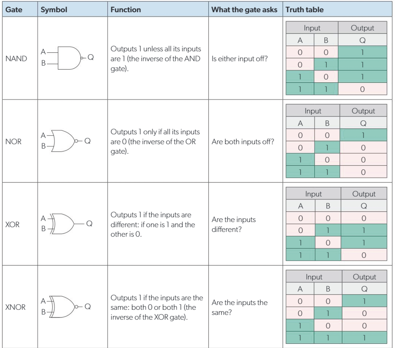
XOR gate
A
B
A XOR B
0
0
0
0
1
1
1
0
1
1
1
0
NAND gate
A
B
A NAND B
0
0
1
0
1
1
1
0
1
1
1
0
NOR gate
A
B
A NOR B
0
0
1
0
1
0
1
0
0
1
1
0
How to construct a truth table
List all input variables.
Write every possible input combination in binary order.
Evaluate the expression step by step.
Fill in the final output column.
Worked example
A
B
C
A AND B
NOT C
Q
0
0
0
0
1
1
0
0
1
0
0
0
0
1
0
0
1
1
0
1
1
0
0
0
1
0
0
0
1
1
1
0
1
0
0
0
1
1
0
1
1
1
1
1
1
1
0
1
How to analyse a truth table
Look for when the output is 1.
Identify which input combinations trigger the output.
Match the pattern to a known gate or logic expression.
Example patterns:
output 1 only when both inputs are 1 → AND
output 1 when inputs are different → XOR
output always opposite of one input → NOT
Logic gate precedence
When no brackets are given, evaluate in this order:
NOT
AND
OR
XOR usually treated at the same level as OR unless brackets specify otherwise.